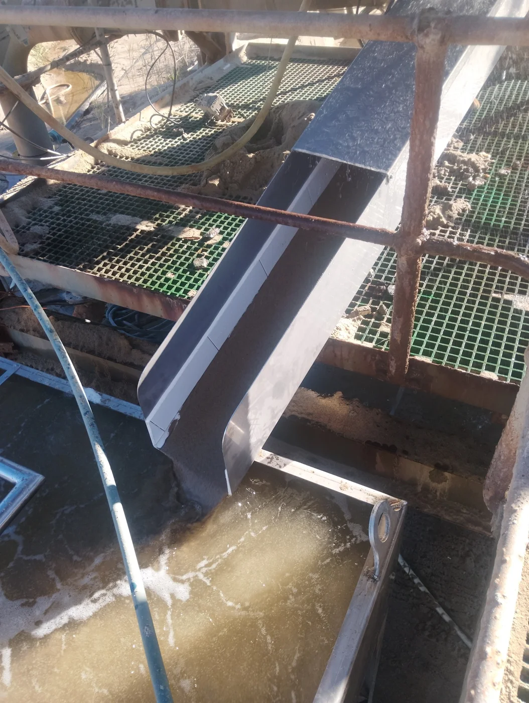
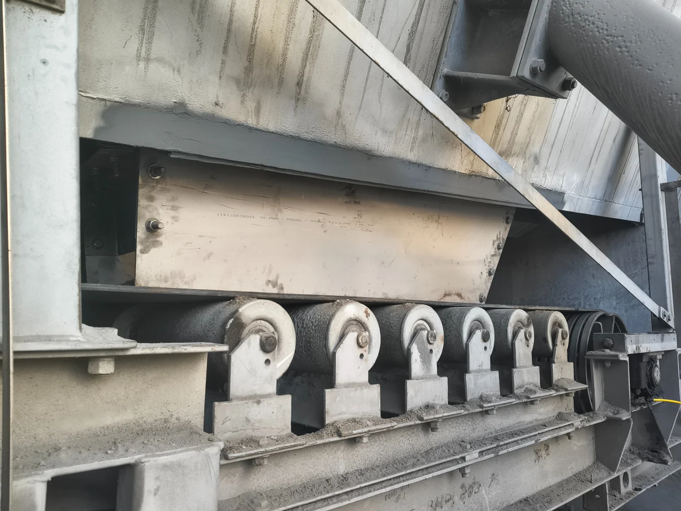
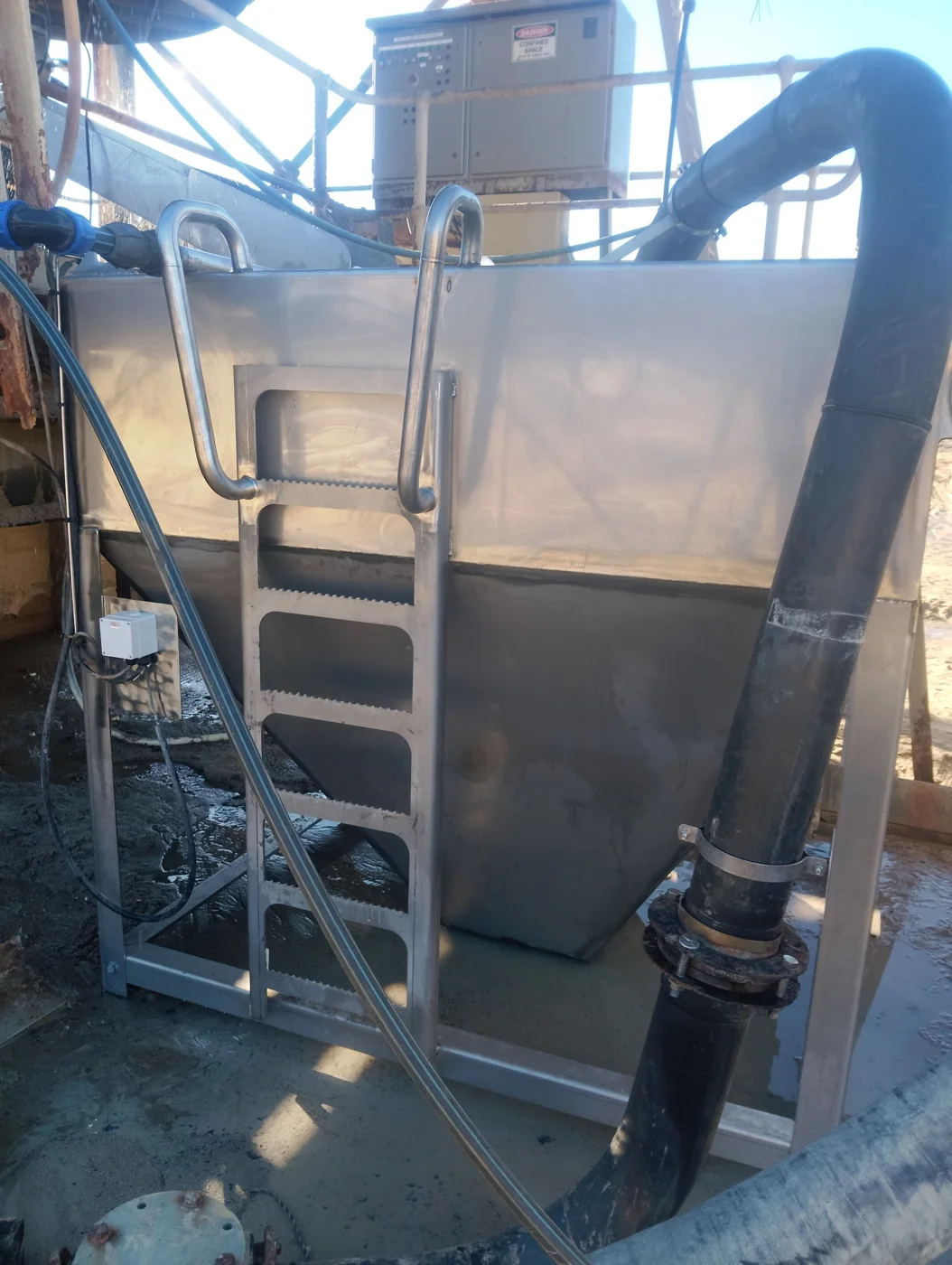
Keep the plant operating.
The screen needed a permanent replacement, while production required an immediate repair.
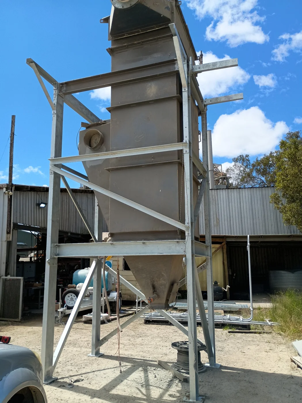
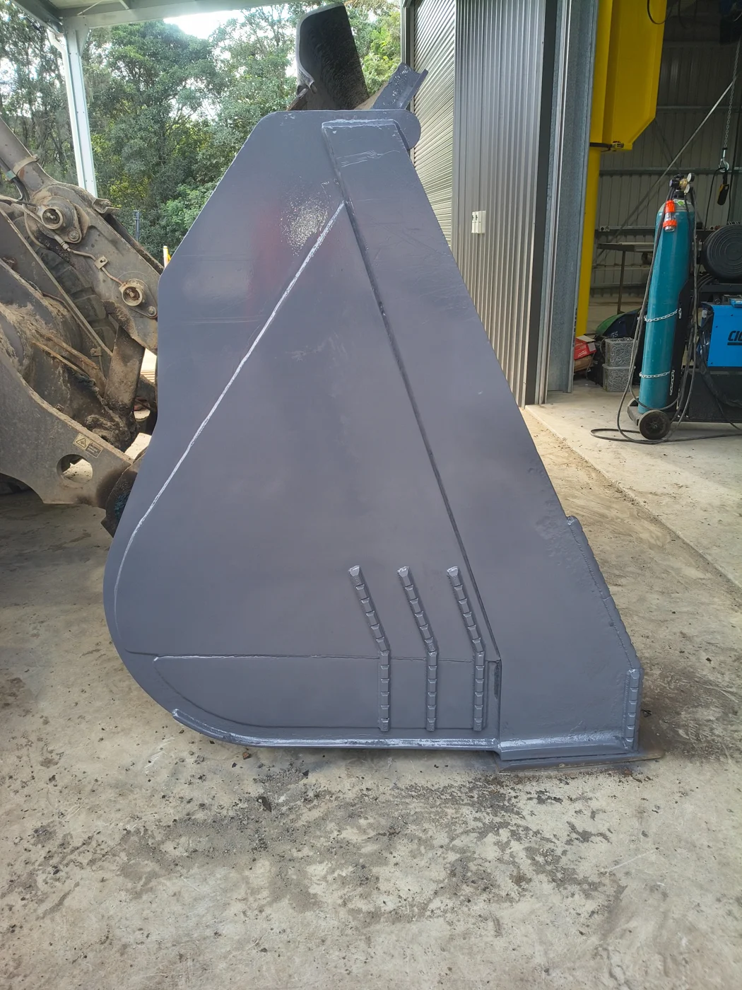
Repair, replace, improve. Work shaped around operating plant and the demands of the site.
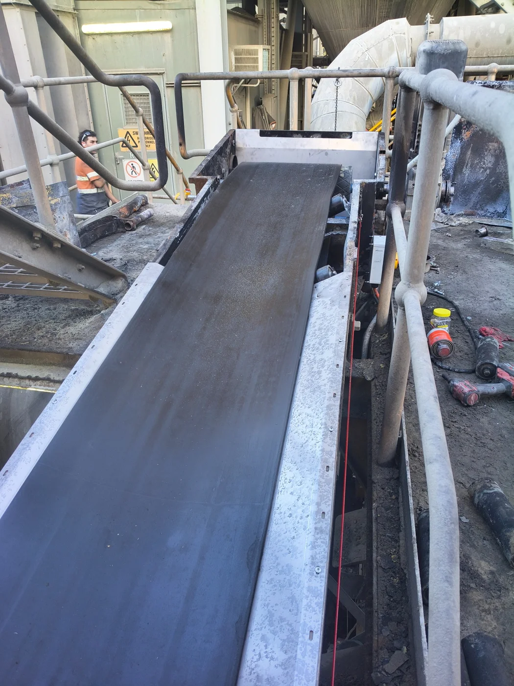
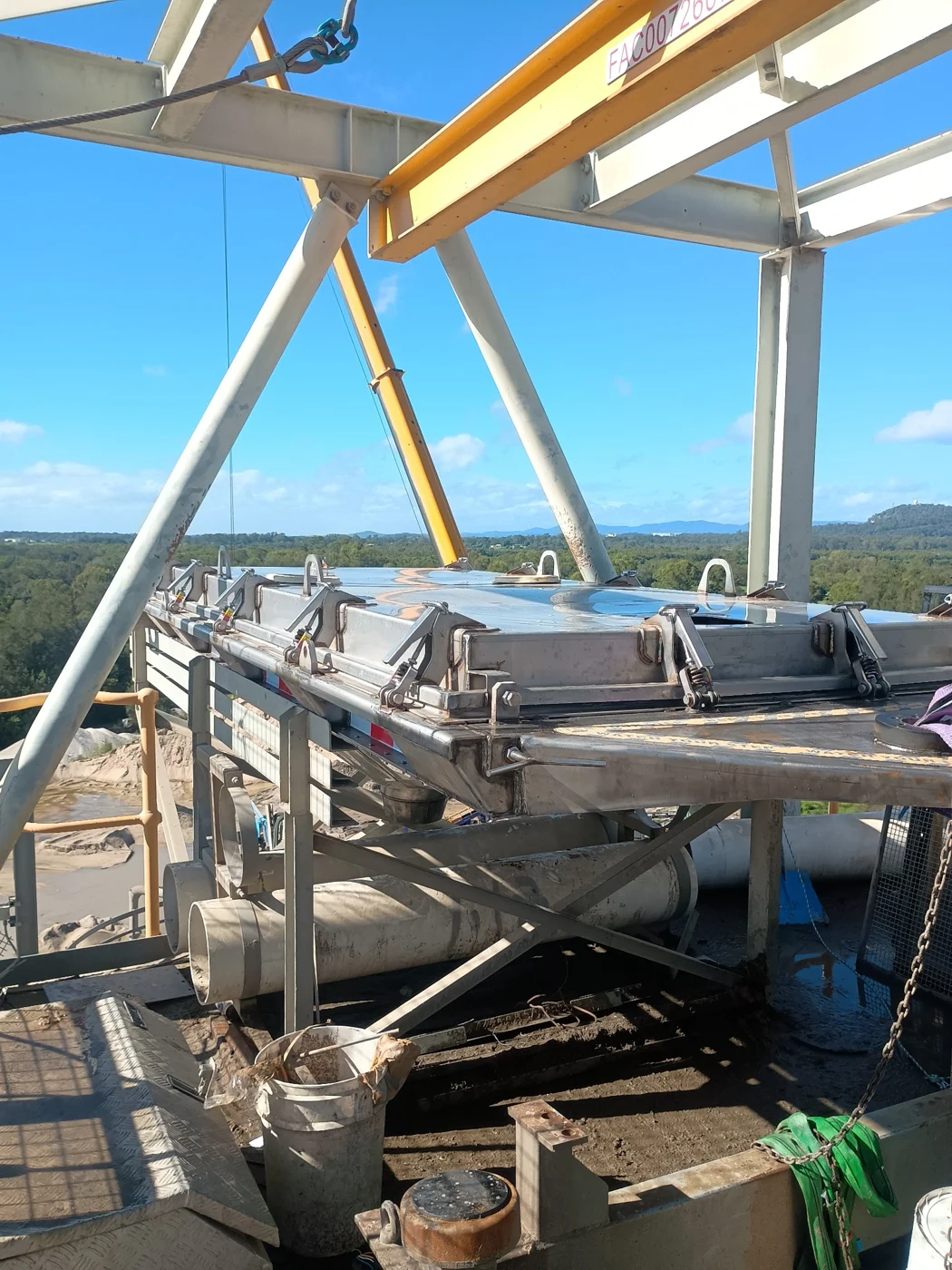
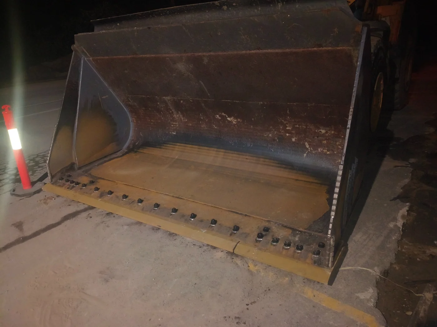
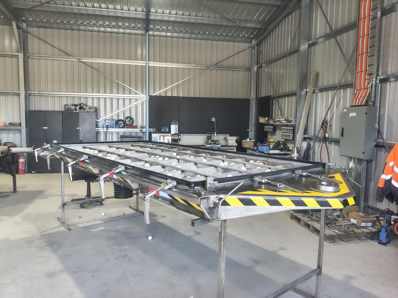
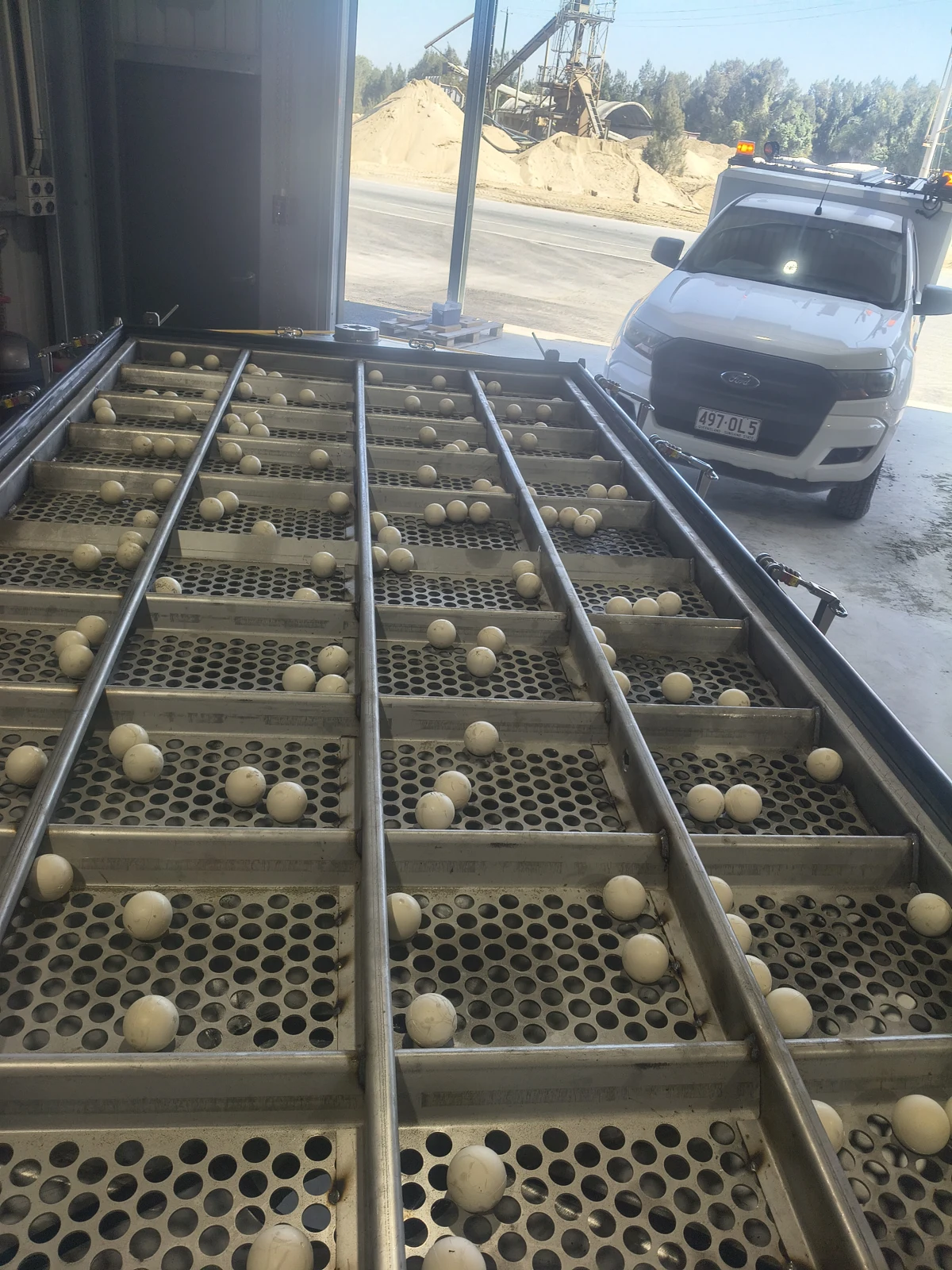
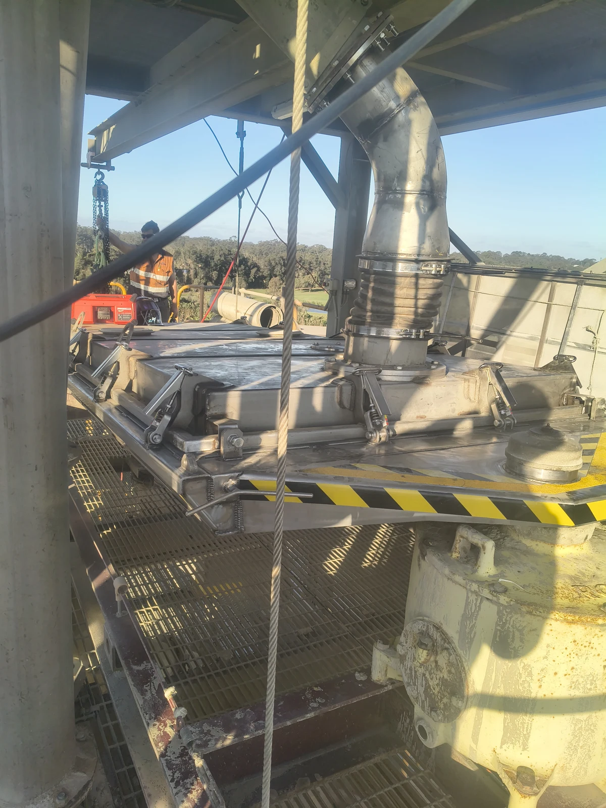
Same-day temporary repairs kept production running. A complete replacement was then fabricated and installed during a planned shutdown, 35 metres above ground.
35 mABOVE GROUNDThe screen needed a permanent replacement, while production required an immediate repair.
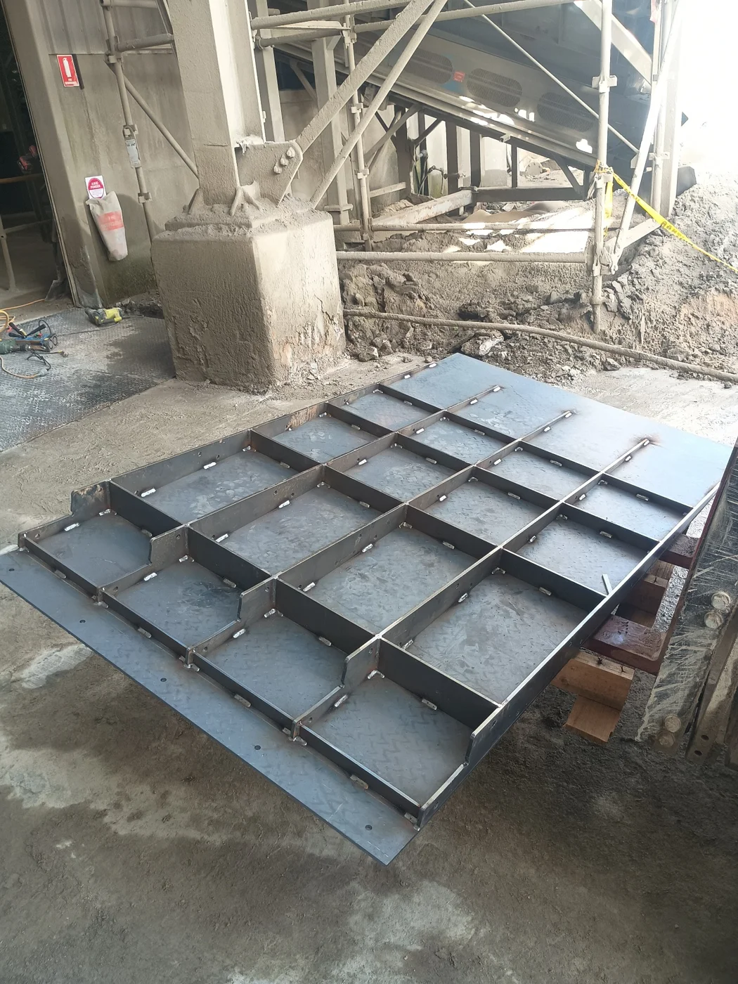
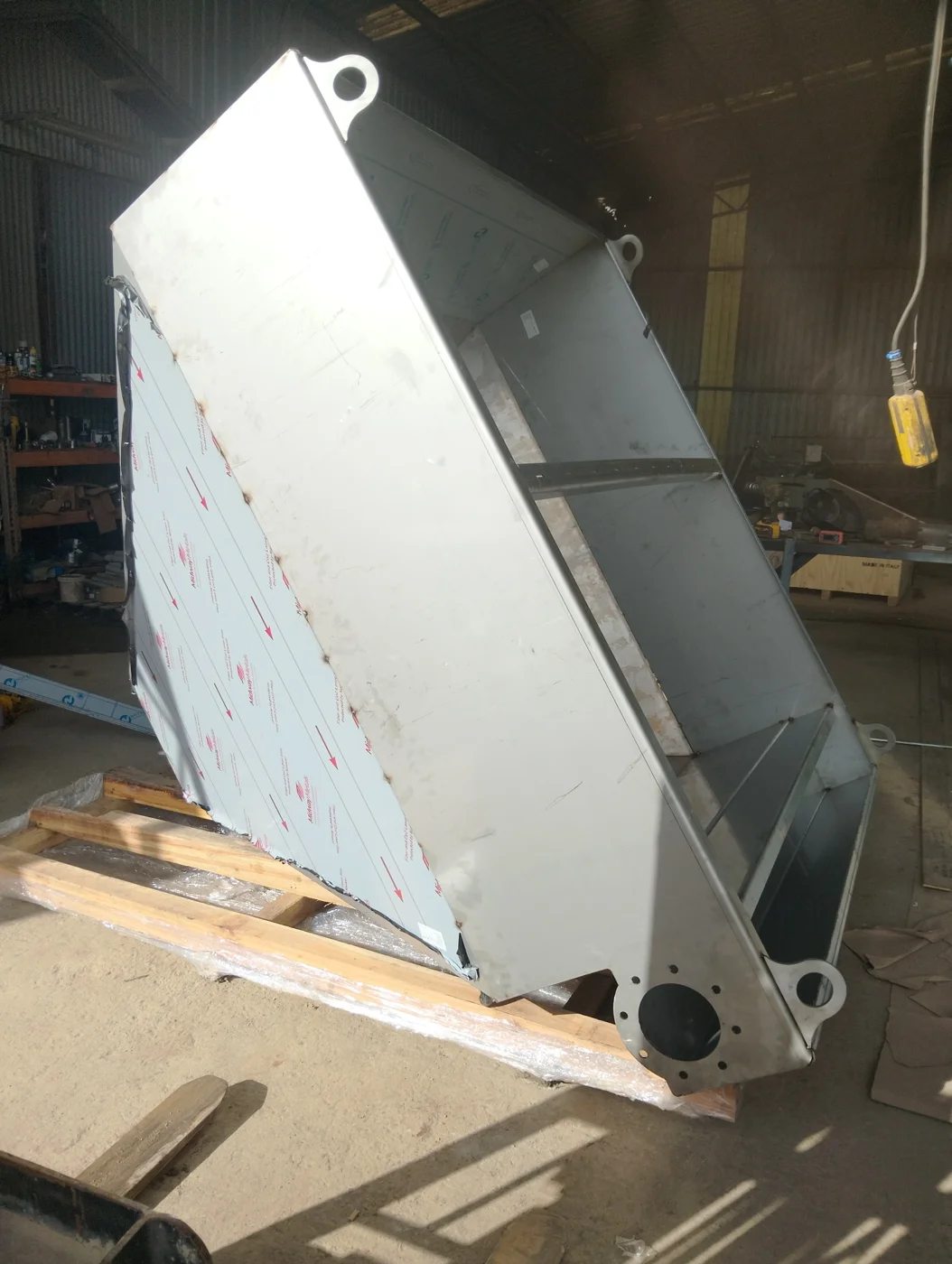
Temporary repairs supported continued operation. Reverse engineering and fabrication prepared the replacement for the planned shutdown.
The completed assembly was installed during the shutdown, working within the access constraints of the elevated plant.
Have worn equipment or an upcoming shutdown?
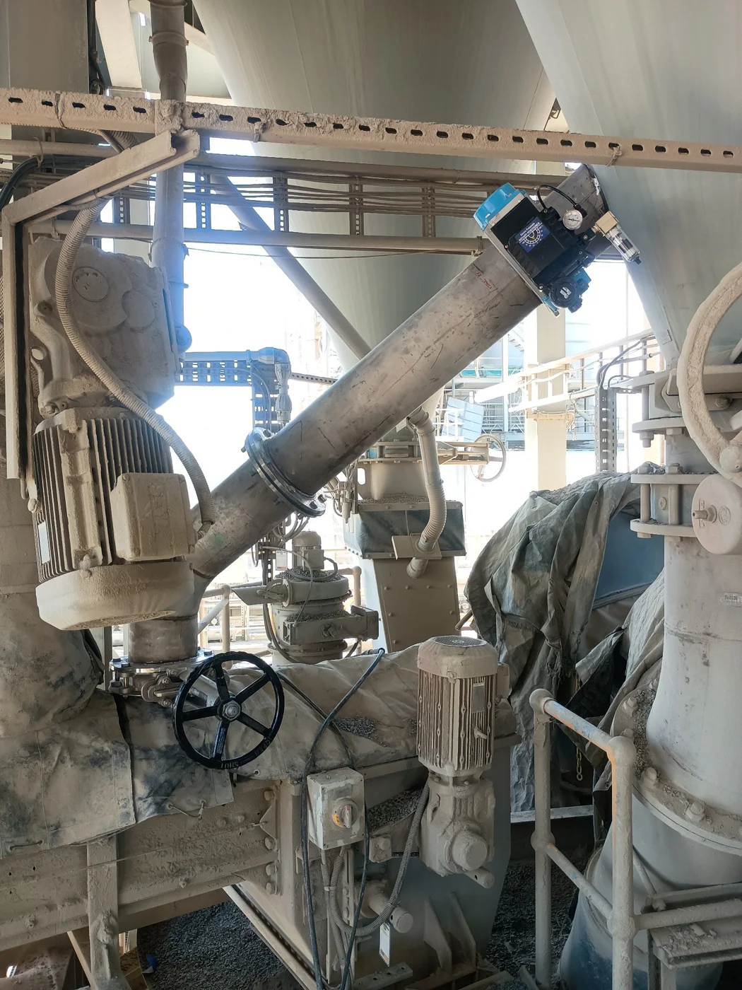
Discuss a repair or replacementAn existing pipe captured by 3D scanning, developed into a CAD assembly and documented for fabrication.
A 3D scan provides the shape and arrangement of the existing component as a design reference.
Pipe sections, flanges, bolt holes and alignment details are brought together in the CAD model.
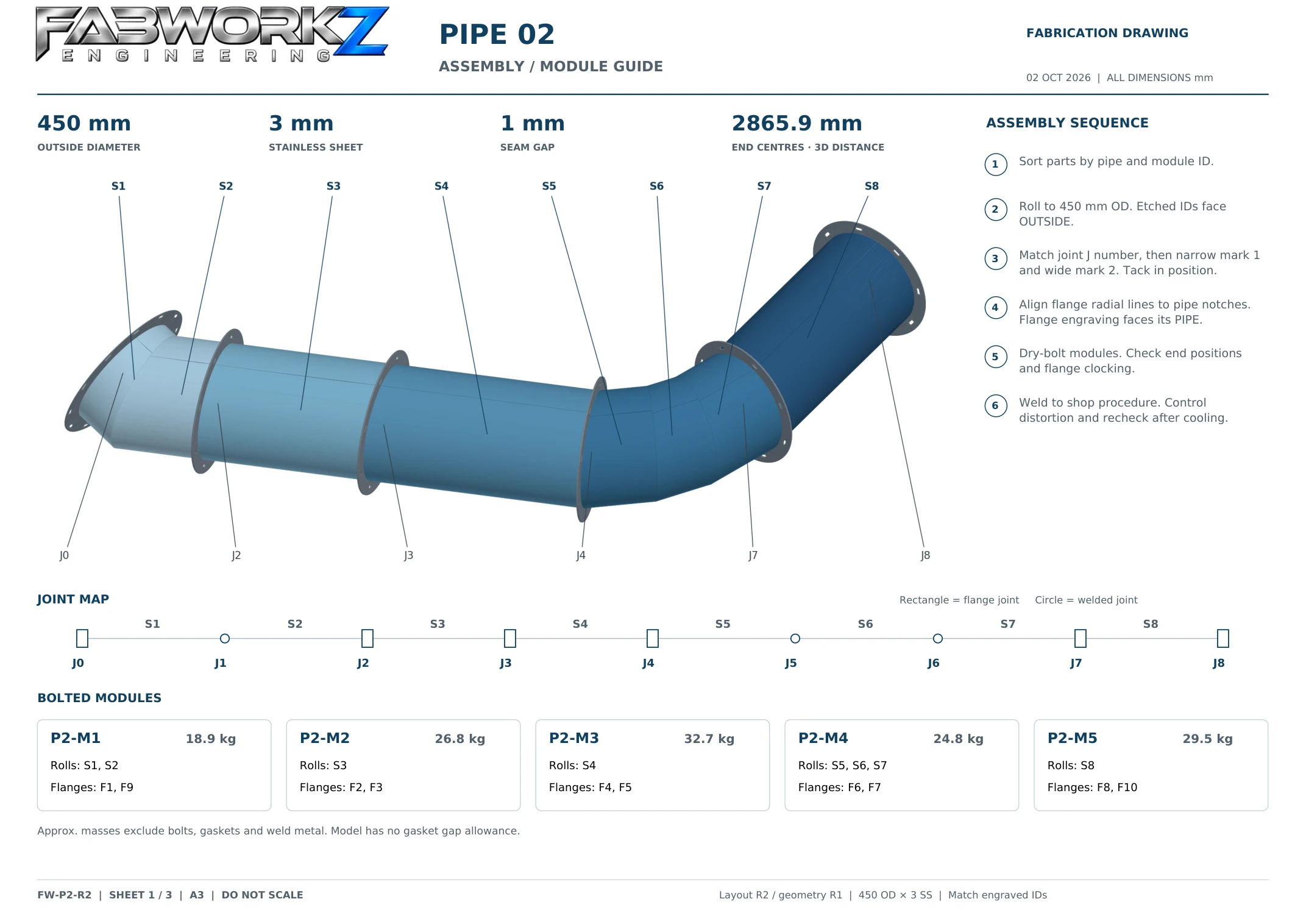
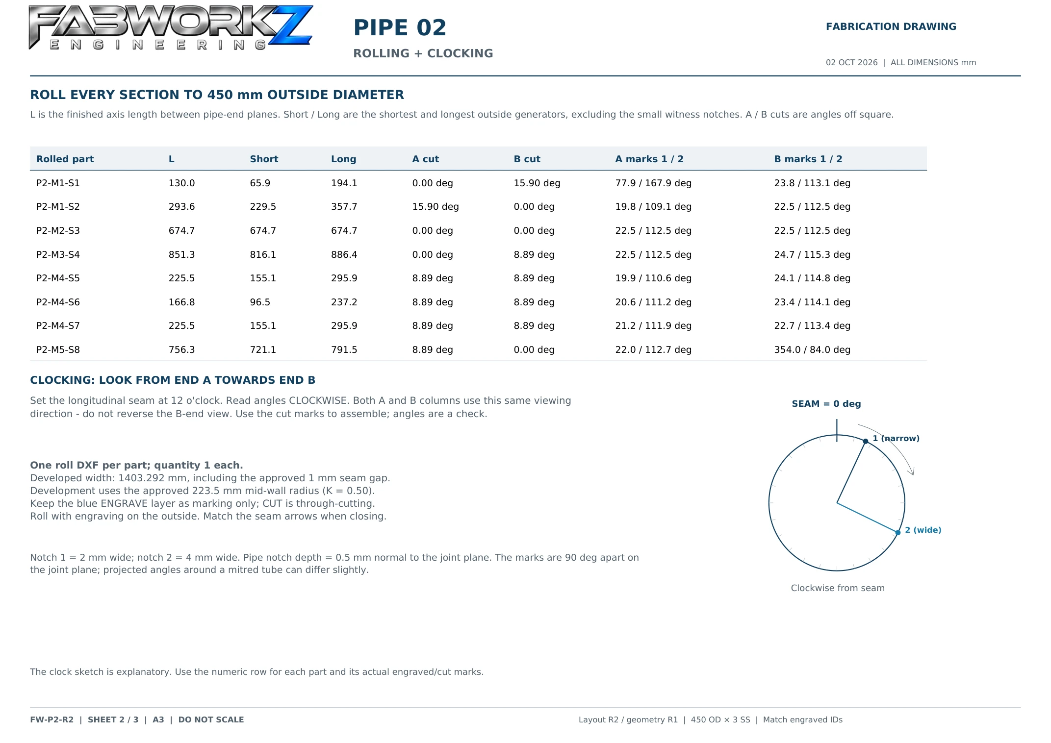
A 3D assembly supported by module, rolling, clocking and joint information for the workshop.
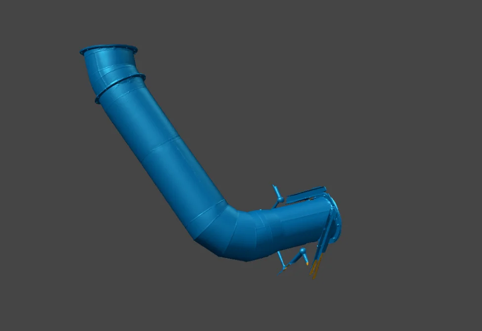
Existing geometry provides the reference for reverse engineering.
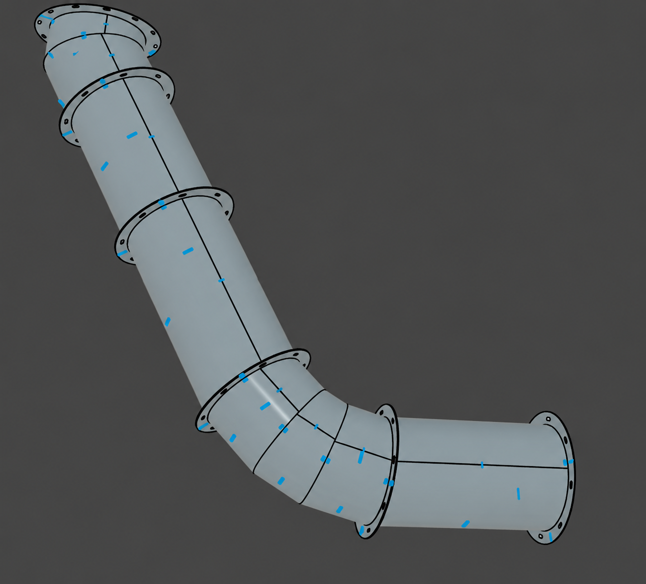
Flanges, pipe sections and alignment details brought together in the model.
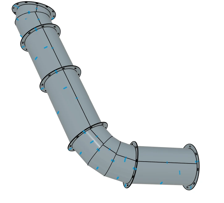
Loading interactive model…
Assembly sequence, rolling and clocking, flange details and joint references. Select a sheet to view it full size.
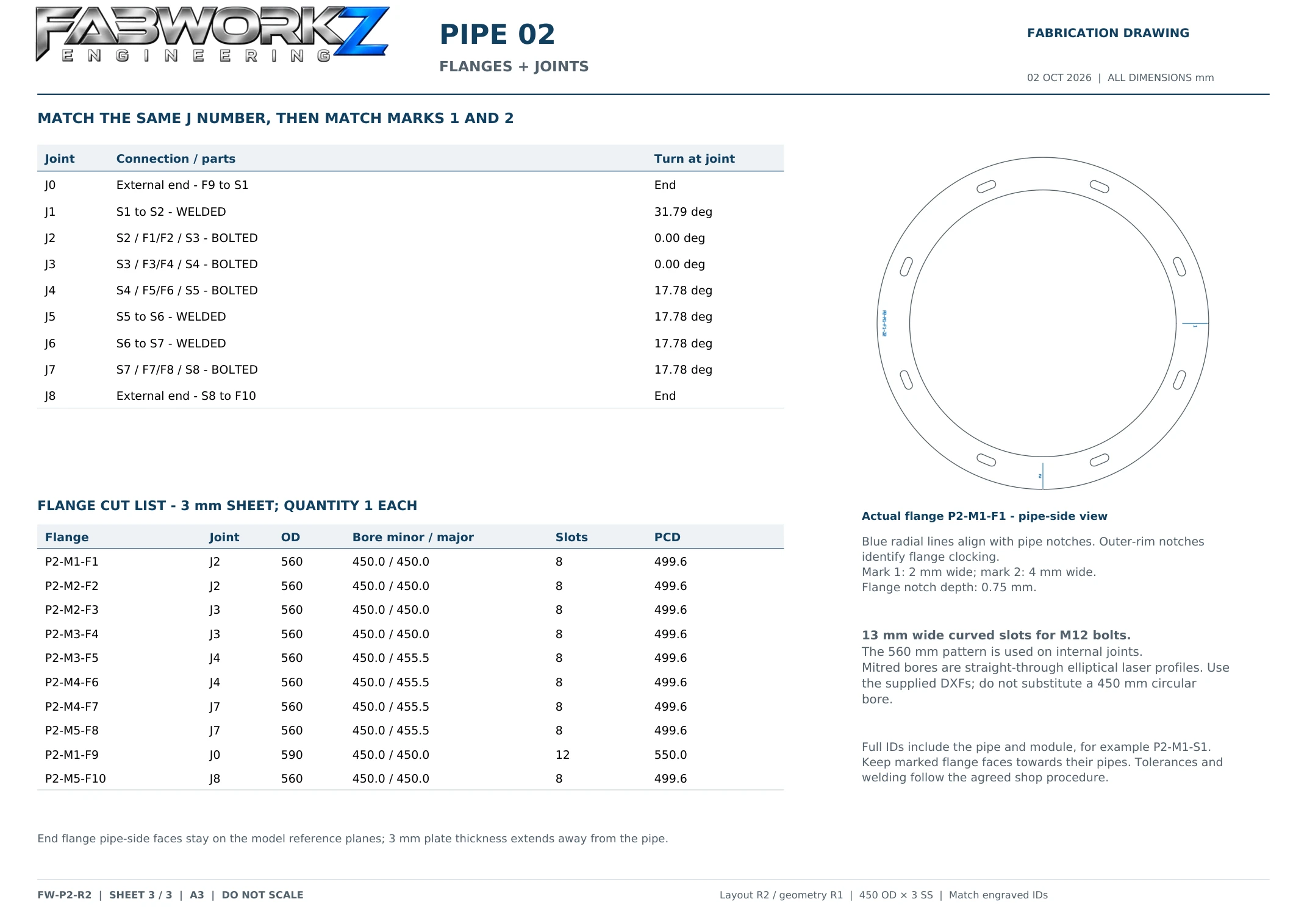
Project example · Displayed for portfolio reference.
Discuss a scan-to-CAD project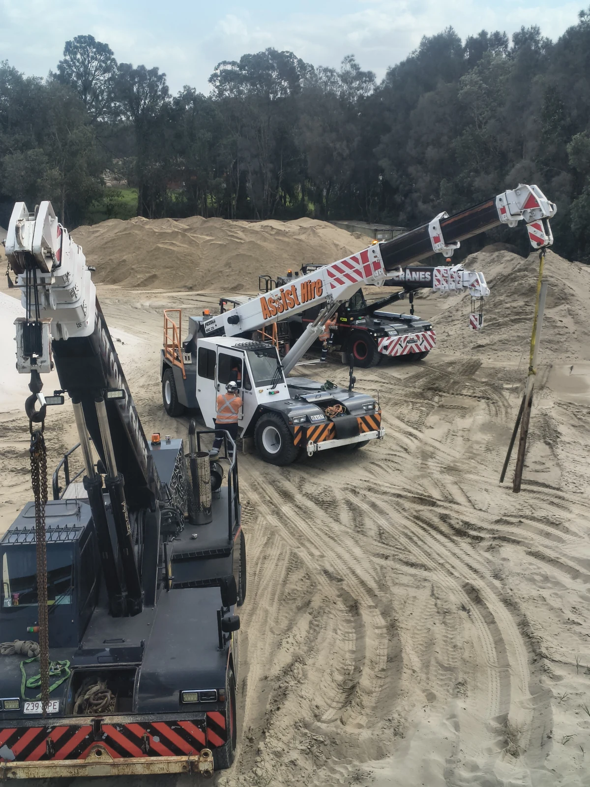
Fabrication and mechanical installation planned around site access, lifting arrangements and the shutdown window.
Discuss your site workIndustrial equipment, fabricated assemblies and practical site work. A closer look at the work behind Fabworkz.